What is Coupling
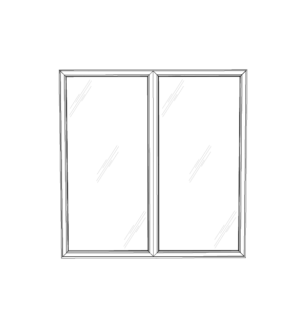
Coupling refers joining two individual units onsite. Those units are normally sent out separately and been mounted together during installation. Coupling was chosen for several general purpose: 1) make larger openings that normally exceeds the maximum size of a unit. When the size of opening beyond the maximum unit size, considering couple two small units together to fill that opening. 2) Strengthen the units to make it able to sustain larger stress from wind load or structural load. For example, when a tall door with side picture field and hinge side is near the picture side, the door needs to be mulled with the picture window to provide enough support strength and preventing deflection on the hinge side. 3) Combine two types of fields that are not able to exist in the same unit. For example, a window can’t not have outswing field and inswing field at the same time, but coupling could connect a outswing window with a inswing window.
Two Methods for Onsite Cupling
There are two coupling options available for Eurotek units. For smaller size coupling that do not require strong joint, we recommend the invisible coupling that could joint two units seamlessly. For coupling that aims at providing stronger joint to take extra load, the profile coupling will be the best choice since it provides extra stiffness to take more load and reduce deflection. Refer to your structural expert to choose proper coupling method for your project.
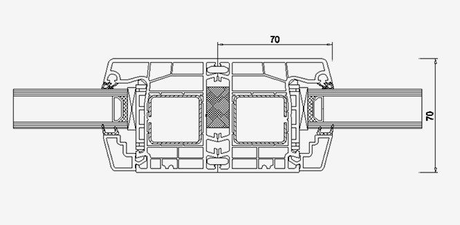
Invisible Coupling
This is a simple coupling way that uses two retainer profiles to keep two units stay alignment. Then fill the middle gap with insulation foam to prevent potential air or water penetration.
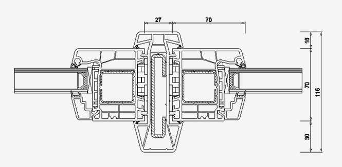
Profile Coupling
This method utilizes an additional coupling profile with reinforcement inside to joint two units. The benefit is extra profile provide extra moment of inertia(up to 54.1 cm^4) and strengthen the joint side under load.
Instructions of Coupling
Determine the required moment of inertia in this coupling case and choose corresponding method of coupling.
Invisible Coupling
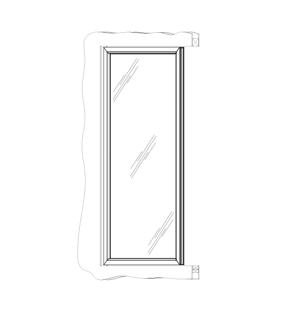
1. Mount the left unit to the structure.
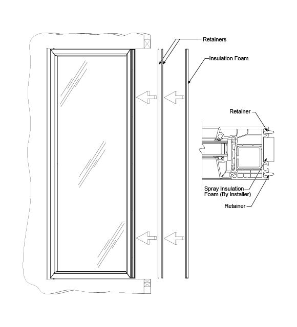
2. Cut the retainers to the size of the unit frame and insert them into the grooves.
3. Installer must spray insulation foam in between the middle gap.
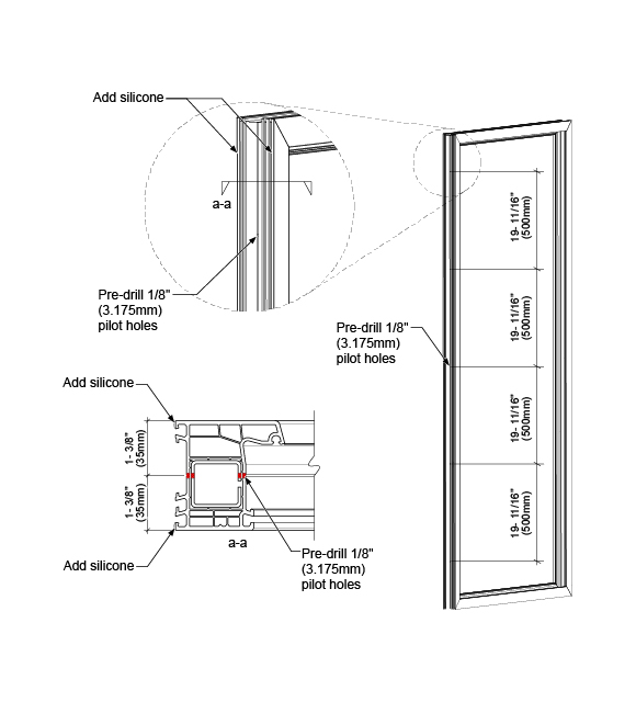
4. Pre-drill 1/8″(3.175mm)pilot holes onto the right unit frame as shown above.
5. Add silicone on the inside edges of the unit frame to prevent potential air and water penetration.
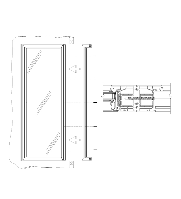
6. Align the right unit frame with the left unit frame and fasten the units together using a No.12 x 3″ long wide round head self drilling screws.

7. Finish securing the right unit frame to the structure, install the glass panel, and seal around the unit frame as required to complete the installation.
Profile Coupling
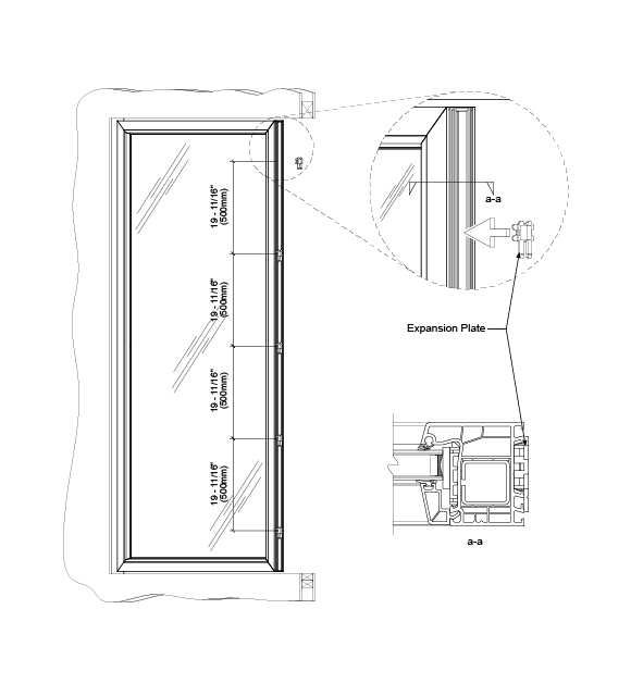
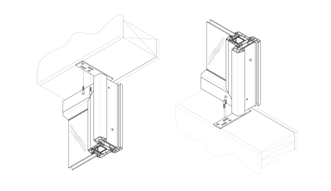
1. Mount the left unit to the structure and Snap-in the expansion plates at 19-11/16″ (500mm) on center as shown above.
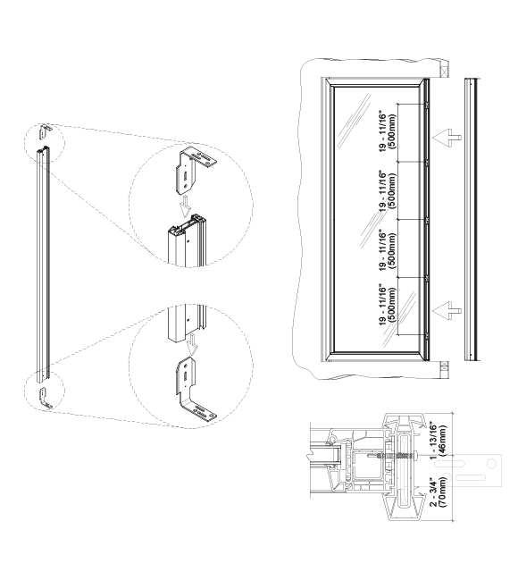
2. Insert the header stanchion bracket and the sill stanchion bracket into the steel reinforcement.
3. Align the coupling to the unit frame and pre-drill1/8(3.175mm) pilot holes and fasten the coupling to the unit frame using M5.5 x 50mm long self drilling screws as shown.
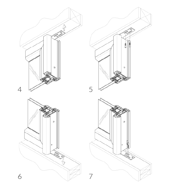
4. Slide the header stanchion bracket flush to the structure.
5. Fasten the header stanchion bracket to the structure using the appropriate fasteners.
6. Slide the sill stanchion bracket flush to the structure.
7. Fasten the sill stanchion bracket to the structure using the appropriate fasteners.
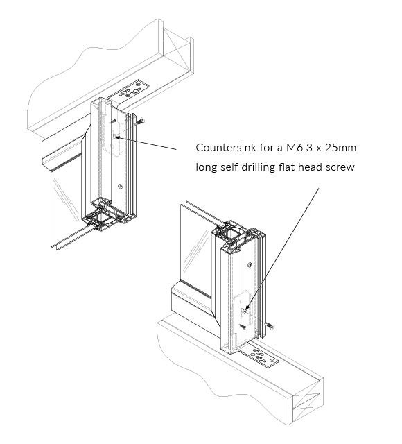
8. Countersink for a M6.3x25mm long self drilling flat head screw and fasten the coupling to the stanchion brackets.
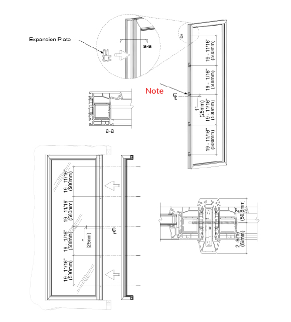
9. Snap-in the expansion plates as shown.
10.Align the right unit frame with the coupling and pre-drill 1/8″ (3.175mm) pilot holes.
11.fasten the unit to the coupling using No.12 x 4″ long wide round head self drilling screws.
NOTE: Make sure to start dimensions 1″ (25mm) above center line to keep CL the screws staggered.
12.Finish securing the right unit frame to the structure, install the glass panel, and seal around the unit frame as required to complete the installation.
Optional Bracket installation.
