1. Introduction
Water penetration test result is one of the most critical aspects of qualifying the on-site windows. The test result determines the water penetration resistance of windows, curtain walls, skylights, and doors when water is applied using a calibrated spray apparatus while simultaneously applying cyclic static pressure to opposite sides of the test specimen. It is crucial to test the water penetration before releasing a new design to production. The water penetration test procedure contains two aspects of the standard procedure. ASTM E331 and ASTM E1105, the former one is for a field test, and the later one is for the lab test. They share the same concept of spray water to the window under a cyclic pressure difference between the two sides of a window. In this essay, we will focus on the lab test of water penetration.
1.1. AAMA Performance Class of Water Penetration
AMMA 502 based on the guidelines from ASTM E1105 and it has specified the evaluation standards of the different class of windows [2]. As Figure 1 shown, the window rating stands for the class number (for R, LC, C, CW, and HC class), each class number has the corresponding Lab pressure and Field Pressure. Those pressures are representing the pressure difference between the opposite sides of the test unit. The corresponding wind speed for each rating class has also been provided with the unit of MPH.
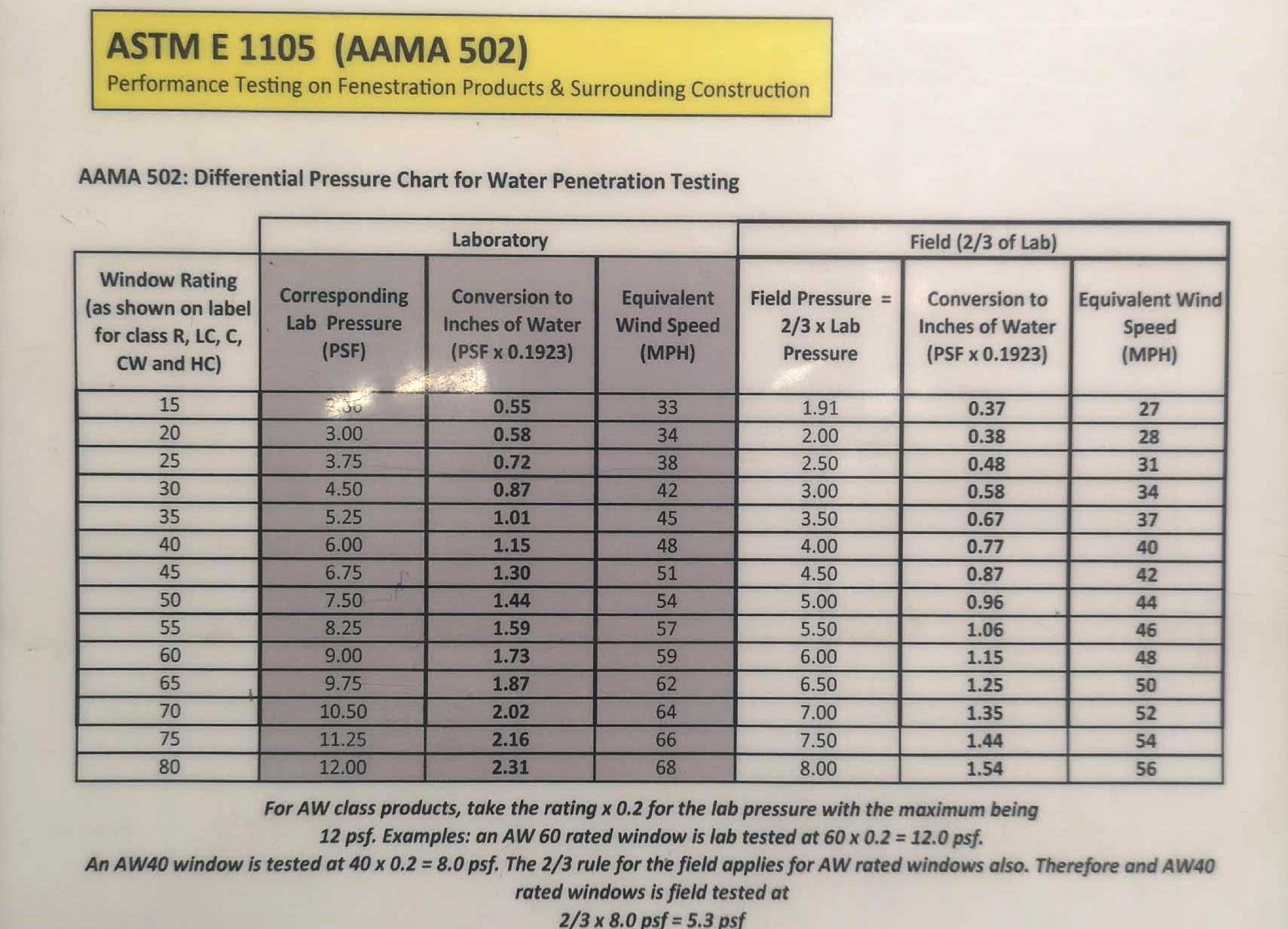
Figure 1. Differential Pressure Chart for AMMA502
The maximum pressure difference within AMMA system is 12 psf for the United States and 15 psf for Canada. The test pressure difference shall no lower than 91 Pa (1.9 psf). The Field test shall be conducted at a test pressure equal to 2/3 of the tested and rated laboratory performance per AAMA/WDMA/CSA 101/I.S. 2/A440 [1].
2. Lab Test Procedure
The purpose of this part is giving a basic description of the procedures and methodology to carry out the water penetration test in the laboratory environment. It is a global reveal of the testing procedure in Fenestration Testing Labs(FTL).
2.1. Methodology of Test
In general, the method to test the water penetration resistance is creating a pressure difference between both sides of the window/door while water is sprayed to the unit. As Figure 2 shown, the testing unit is mounted on a wall with a chamber located on the inside to create an air isolated environment. The air system behind it could create a low or high air pressure and therefore result in a pressure difference between the two sides of the unit. A water spray rack is used on the outside of the unit to provide the required amount of water to simulate the rain.
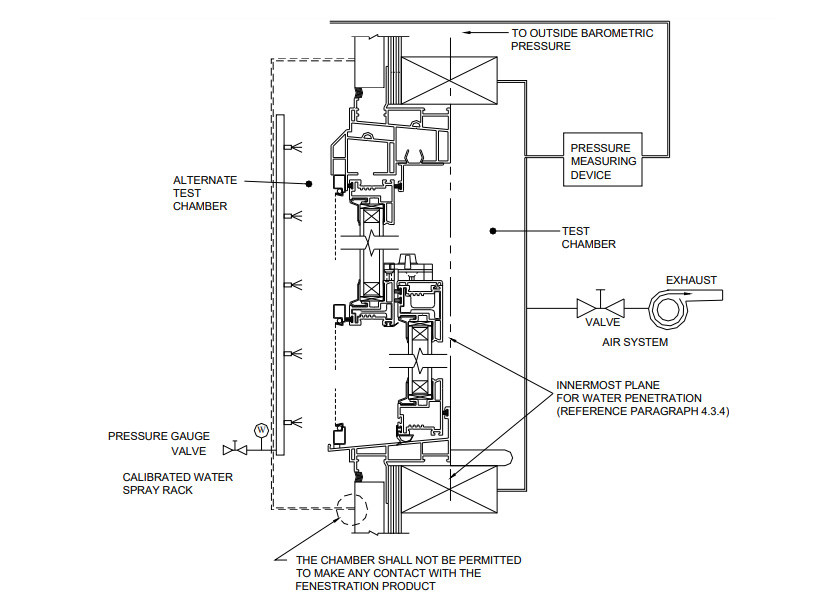
Figure 2. Setup of the test system
2.2. Prepare the Testing Unit
As shown in Figure 3 a chamber is required to provide the sealed space needed to create a pressure difference. Therefore, special preparation is required in order to simplify the test procedure. The unit needs to be nailed on and surrounded by 2×8 inch wood bar. Those wood bar could help on forming a sealed chamber during the test which requires a complete silicone seal of the connection between the window/door with the wood bar. The silicone would prevent any air and water leakage through the connection.
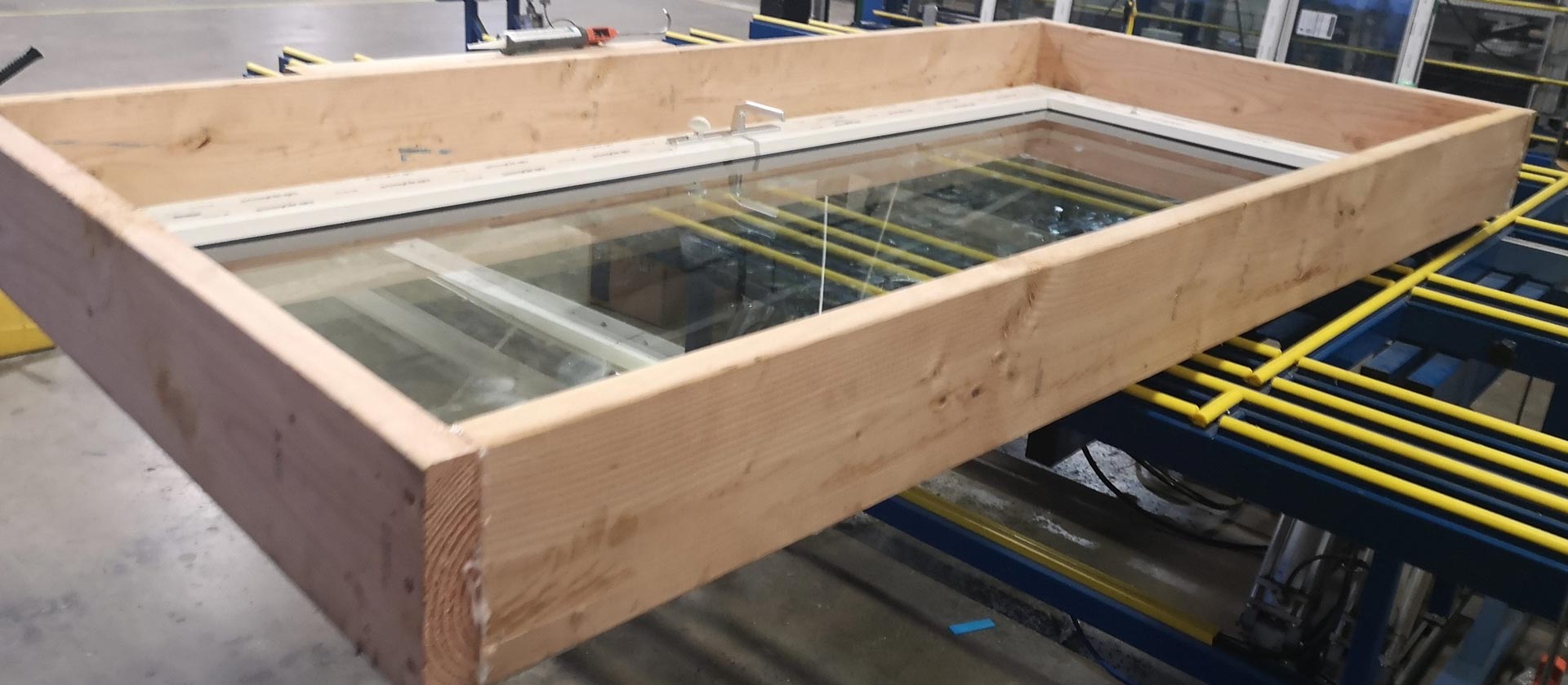
Figure 3. The test unit surrounded by wood bar
2.3. Main Equipment Used During Test
2.3.1. The Testing Wall
Figure 4 is the central equipment for the water penetration test. It is made of transparent material to ensure any personnel could check the testing progress from the inside. Air pipes connect the air system with the wall and make it able to make pressure difference. On the wall, there are many square metal clips and which would be used to fix the prepared unit.
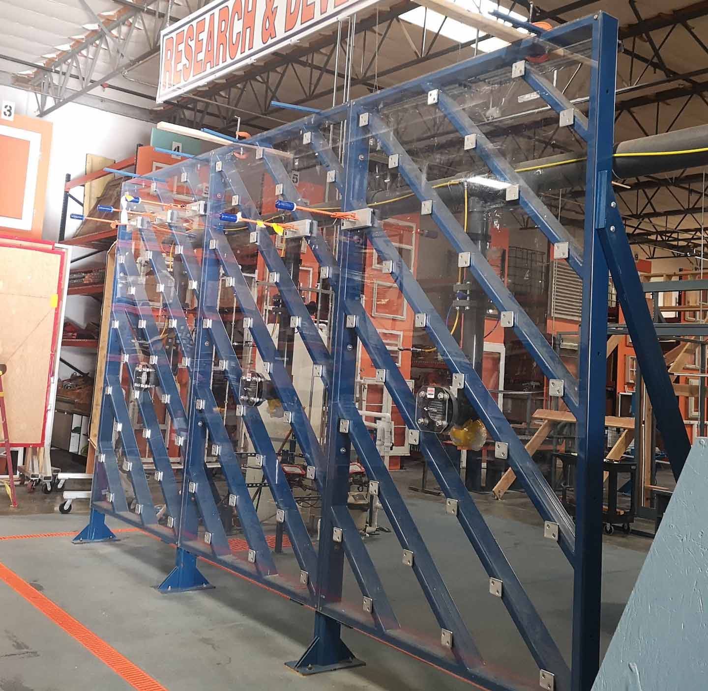
Figure 4. The testing wall
The prepared unit would be mounted on the wall to create the seal chamber. A strip of double-sided glued foam is applied between the prepared unit and the testing wall to ensure the seal. Clamps are mounted around the tested unit and slide into the clips to hold the unit firmly with the testing wall.
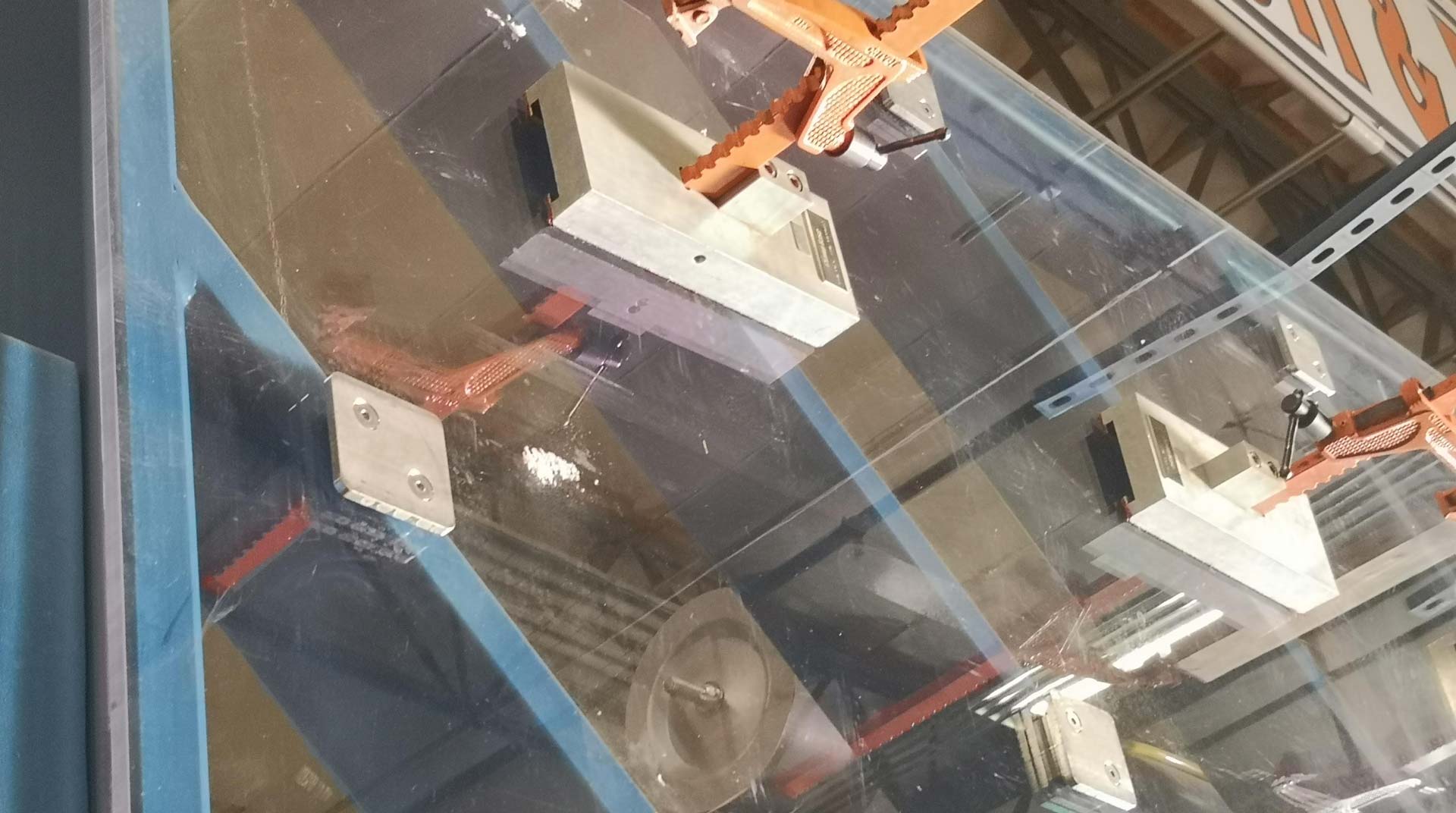
Figure 5. The clamps used to mount tested unit
2.3.2. The Air System
The Air system is the equipment that creates a pressure difference between the two sides of the testing unit. With a properly sealed chamber, the system could always maintain the required pressure level. It usually comes with a digital controller to set up the target pressure level, but if it does not apply, merely a pressure gauge with blower motor controller could help on manually adjust the pressure.
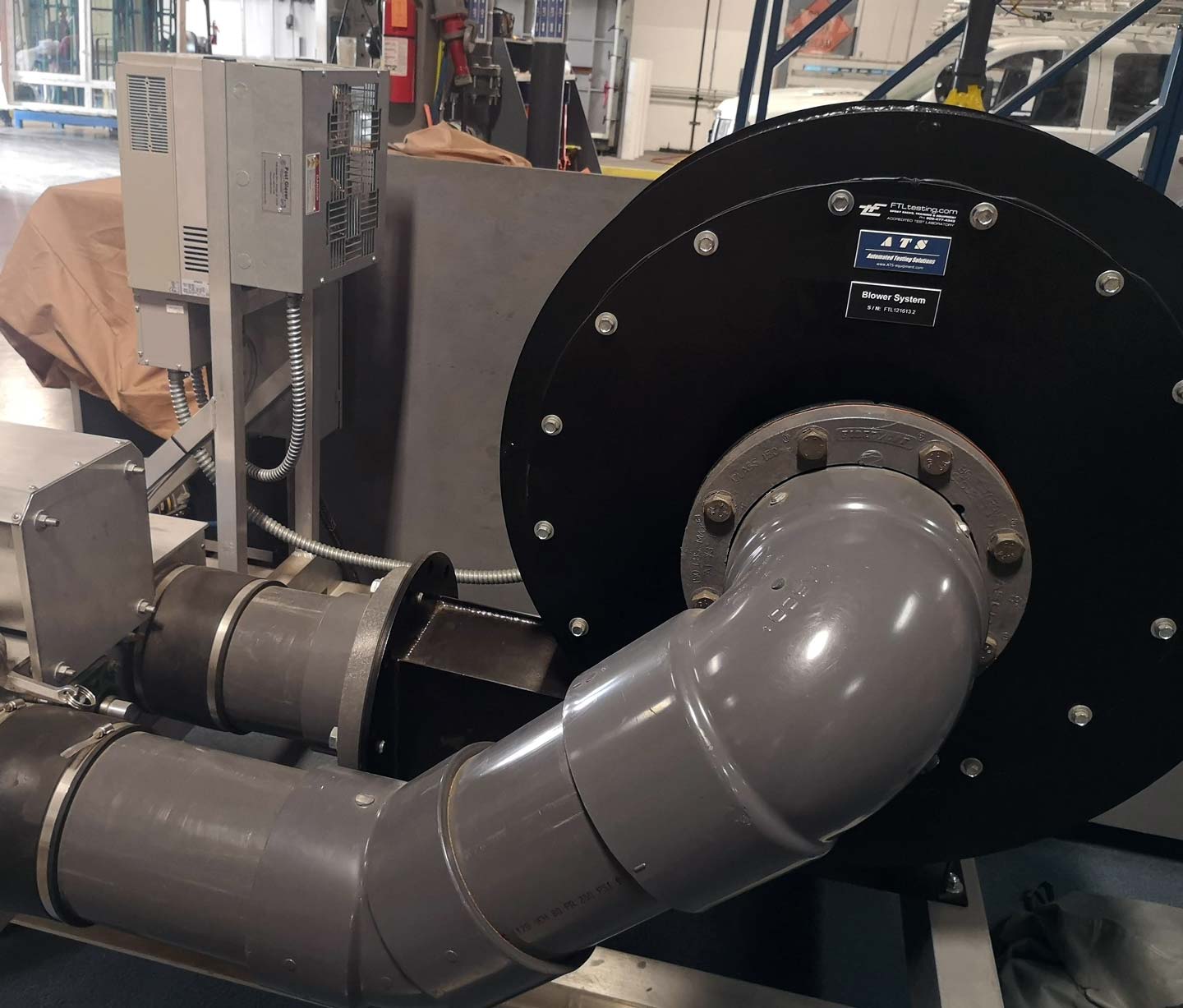
Figure 6. The air system used in FTL
2.3.3. Laser Level
The laser level is used to ensure the tested unit is mounted correctly. It is essential to simulate the real performance of unit after installation to the job site. Therefore, the mounted unit on the testing wall should be measured by the laser level. An additional adjustment may be needed to apply to make sure the unit is mounted in a rectangular manner.

Figure 7. The laser level
2.4. Test Procedure
This part would be a brief explanation of the whole process start form mounting of the unit and record result. A complete test contains four 5-minute pressure cycles. Between each cycle, there would be a 1-minute break while the water spray rack keeps running. Any drop of water appears inside would result in the test to be failed. Refer to Figure 1 the tested unit will get the highest rating it has ever passed.
2.4.1. Set Up the Test Unit
The test unit is pushed against the wall to create a chamber. The foam is applied, and the clamps could fix the unit and hold it with the wall. As shown in Figure 8, a white plastic film is taped to the unit to ensure the sprayed water would focus in the window fields. In order to keep the unit mounted correctly, the laser level should be used to adjust the window before installing the top and bottom clamps.
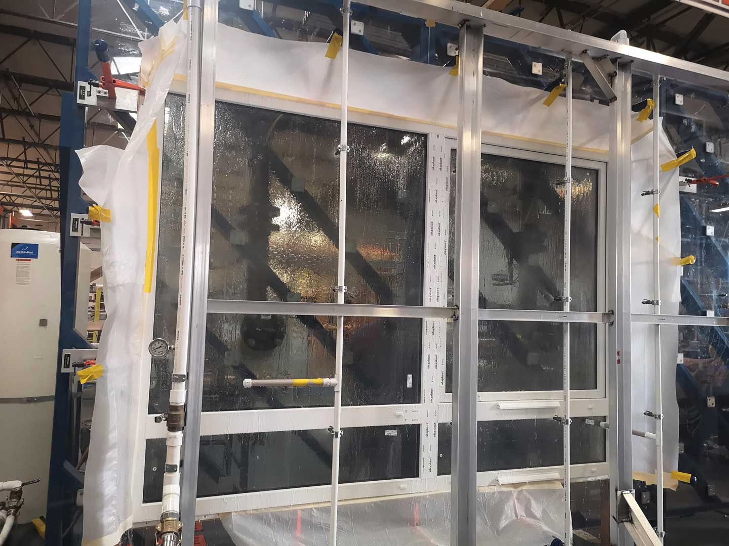
Figure 8. A fully set testing unit
2.4.2. Launch the Water Spray Rack
Figure 8 demonstrates how the spray rack works with a test unit. Generally, a spray rack would include the water supply pipe, the calibrated valve to control the feed speed of water and many nozzles to spray water. All of those components are built for uniformly distribute the water to the exterior of the unit in a minimum flow rate of 3.4 L/m2⋅min (5.0 U.S. gal/ft2⋅hr). This flow rate corresponds to a rainfall of 20.3 cm/hr (8.0 in/hr) [3].
After the spray rack launched, an immediate check would happen to locate any possible leak of the specimen. This period would also ensure the water spray is continuous and stable and the whole system is ready to start the test cycles.
2.4.3. Launch the Air System
As mentioned above, four cycles of the test will be carried out, and each of them would last 5 minutes. The time count starts when the pressure difference reaches the target value shown in Figure 1. Noted that the target value stands for the exterior pressure minus the interior pressure, which means the air system trying to suck in the water. The air system would ensure the pressure difference maintains in stable value. A continuous check will happen during the 5 minutes to locate any leak from the specimen. A flashlight is usually used to help identify water drop by the reflection of light.
2.4.4. Cycles of Pressure and Test Result
In total 4 cycles of the test will be carried out to fully simulate the rainy weather condition, in between them is a 1-minute break. During the break water will be continuously sprayed into the unit. Noted that there is only pass or fail in the test. Water leakage in any cycle will be considered to fail the test. The water penetration is a test for a long-term waterproofing. Any water drop appears inside already indicates that the water has passed all barriers in the unit, therefore the drain system is not capable in this pressure level. Start with the lowest expected pressure level, a test unit will keep challenging a higher level until the test failed. The test result would be the last test that has passed. Therefore, a common method to maximize the result will be to minimize the step when the pressure is approaching the expected highest pressure.
3. Conclusion
All procedures in the water penetration test aims at create a critical environment to suck in the water. It could be taken as a loading test of water penetration. The test is extremely useful not only for sale products to professional construction project, but also am important tool to locate the weak point of the unit and find out any design or manufacture issue within the production line.
Acknowledgment
I would like to thank Fenestration Testing Labs for providing test related description and technical data information. Also a special thank to the all members Value who involved in this lab test for the strong support.
Figure 1. Differential Pressure Chart for AMMA502
The maximum pressure difference within AMMA system is 12 psf for the United States and 15 psf for Canada. The test pressure difference shall no lower than 91 Pa (1.9 psf). The Field test shall be conducted at a test pressure equal to 2/3 of the tested and rated laboratory performance per AAMA/WDMA/CSA 101/I.S. 2/A440 [1].
References
[1]American Architectural © American Architectural Manufacturers Association. “Water Resistance Testing of Windows and Doors.” 2010. http://www.aamanet.org/upload/file/Water_Resistance_Testing_of_Windows_and_Doors-FINAL.pdf
[2]Inc. (BDG) Building Diagnostics Group. “AAMA 502.” http://www.bdg-usa.com/aama-502.html.
[3]RWC, RRO, PE, CDT Robert Hinjosa RRC. “Designing, Specifying, And Testing Windows for Water Penetration Resistance: The Effects Of Changes in AAMA 502 Test Standard.” 2010. http://rci-online.org/wp-content/uploads/2010-04-hinjosa.pdf.